Auxiliary Power Layer
for Remote
Telecom Towers.
A continuity infrastructure layer designed for remote macro and small-cell sites where diesel logistics has become an architectural risk rather than an operational cost line. Engineered to operate beneath your existing RAN equipment as auxiliary tower-site power infrastructure — not a replacement for your network supplier.
We built this for the operators and TowerCo Directors who already know the answer to one question: what does it cost when the fuel delivery is late and the site is unreachable in winter? The regulatory stack now codifies that risk. The architectural response is overdue.
Vitaly Peretyachenko · Founder, VENDOR.Energy
Diesel logistics at remote tower sites
has moved from operational cost line
to balance-sheet item.
For three decades, diesel-by-default at remote macro and small-cell sites was an operational nuisance managed by fleet procurement. By Q2 2026, the convergent regulatory stack — NIS2 supply-chain security, CSRD ESRS E1 transition plan capital allocation, EU Battery Regulation 2023/1542, CER critical-entity designation, GSMA Mobile Net Zero pace gap — has converted that line into a capital architecture variable. The pain below is the operational reality your Head of Energy and TowerCo Director already manage. The regulatory pressure is what makes 2026 the conversation window.
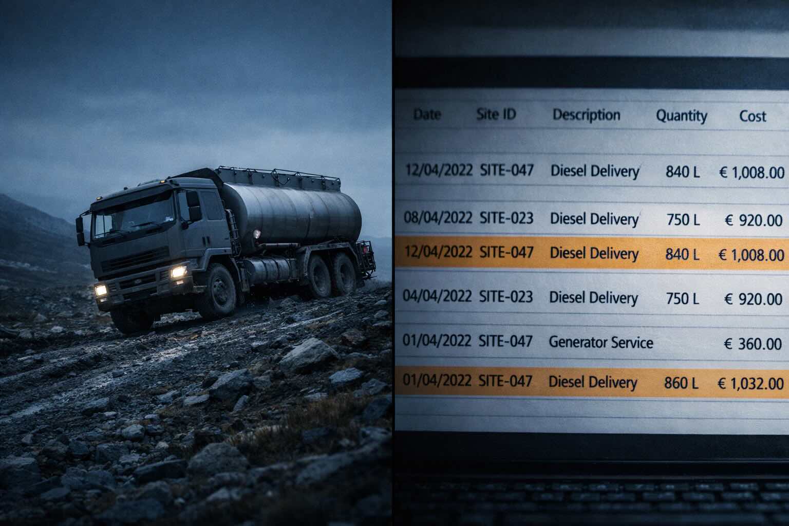
Diesel delivery is the recurring cost the network does not control
Fuel procurement, transport to weak-road or no-road sites, on-site storage, generator maintenance and theft replacement form a logistics chain that compounds with every remote site added to the portfolio. At industry scale, GSMA documents this as a structural cost driver across off-grid telecom infrastructure, unresolved by RAN equipment efficiency improvements.
Stationary combustion at remote sites is now a disclosed Scope 1 emissions line
Under CSRD ESRS E1, Wave 1 telecom incumbents are reporting Scope 1 emissions with limited assurance from FY2025, escalating to reasonable assurance by FY2028. Diesel run-rate on remote macro and small-cell sites appears directly in the transition-plan capital allocation disclosure — and surfaces in MNO Scope 3 reporting through TowerCo colocation cascades.
Fuel-logistics resilience is now a Board-level cybersecurity-adjacent obligation
NIS2 Directive 2022/2555 places telecom under essential-entity scope with Article 21 supply-chain security and business-continuity obligations covering physical infrastructure dependencies. Article 32(6) attaches personal management liability. Fuel theft, delivery disruption and weak-road dependency at unmanned remote sites are no longer logistics incidents — they are supervisory-relevant resilience events.
Some remote sites have no road, weak grid, or cascading outage exposure
Mountain relays, island installations, seasonal-track and helicopter-only sites carry structurally unreliable fuel logistics that compound under load-shedding and weak-grid cycling. Under CER Directive 2022/2557, 17 July 2026 marks the critical-entity designation deadline across Member States — extending power-continuity obligations beyond the legacy battery-bank backup horizon.
The architectural inevitability is dated.
2026 is the conversation window.
Five regulatory anchors converging on telecom auxiliary tower-site power architecture between Q1 2026 and FY2028. The pace gap reported by GSMA confirms operational emissions reduction must roughly double to meet the 2030 industry target — and RAN equipment efficiency progress alone does not close it.
Auxiliary tower-site power infrastructure.
Different architectural class from your network supplier.
VENDOR.Max operates on the auxiliary infrastructure layer adjacent to and beneath the RAN equipment provided by Tier-1 OEMs — Ericsson, Nokia, Huawei, ZTE, Samsung. These suppliers provide the radio-access network primary load: base stations, macro-cells, small-cells, antennas, baseband processing. VENDOR.Max addresses the auxiliary tower-site power layer that sits underneath. Different architectural class, complementary not competing.
Auxiliary tower-site power, beneath RAN equipment
Designed to integrate with existing tower-site electrical architecture: utility connection, rectifier interface, BESS coupling points, SCADA monitoring touchpoints. The auxiliary layer addresses the resilience and continuity functions that legacy diesel-by-default architecture has handled since the mid-1990s remote-site expansion.
2.4–24 kW design envelope for macro and small-cell profiles
Engineered to operate across the full European remote-site distribution: rural macro, suburban macro, small-cell, hub-site. Climate-envelope characterization, security-profile compatibility (NIS2 Article 21), and site-availability tracking are part of the validation framework under pilot conditions.
Tier-1 RAN OEMs are partners, not competitors
The RAN-OEM-agnostic interface is a fundamental design constraint, not a retrofit. Ericsson, Nokia, Huawei, ZTE and Samsung equipment operates on top of the auxiliary tower-site power infrastructure layer VENDOR.Max addresses. The architectural conversation respects the multi-vendor reality of the institutional aggregator's site ecosystem.
TRL 5–6 pre-commercial validation stage
Over 1,000 cumulative operational hours documented at TRL 5–6 under controlled conditions, including a 532-hour continuous segment. Independent third-party metrology engagement is part of the certification roadmap. Pilot deployment proceeds in parallel with existing site infrastructure — diesel system retained as backup during the operational verification window.
- Not RAN equipment of any kind
- Not a base station, macro-cell, or small-cell
- Not 5G radio or 6G radio
- Not an antenna or baseband processing equipment
- Not Tier-1 RAN OEM equipment-class
- Not a grid replacement — operates alongside utility connection
- Not a primary process equipment or data-center IT load primary UPS
- Not a consumer mobile, handset, or B2C retail product
The auxiliary tower-site power layer
becomes a separable infrastructure asset
inside the TowerCo capital architecture.
Under CSRD ESRS E1 transition plan capital allocation, NIS2 supply-chain security cascade and EU Battery Regulation 2023/1542 documentation requirements, the auxiliary tower-site power architecture is no longer a buried OPEX subcomponent of colocation rent. It is an independently documented, separately financeable, separately negotiated infrastructure asset class — and the architectural conversation moves into the emerging T-ESCO / captive energy-services pattern visible across European TowerCo strategy.
T-ESCO segregation: auxiliary power as captive revenue category
An emerging T-ESCO / captive energy-services pattern visible across European TowerCo strategy structures auxiliary tower-site power as a captive Energy Service Company offering to the MNO tenant — creating explicit revenue and margin allocation between colocation and energy services. The auxiliary architecture decision in 2026 sets the cap-rate framing for the T-ESCO segment in 2027–2028 disclosure.
MSA renegotiation: energy services explicit, not buried in rent
Master Service Agreement structures where energy CapEx passed through implicitly to MNO tenant via colocation rent escalator are compressing under MNO consolidation and CSRD documentation overhead. A documented auxiliary architecture decision creates negotiation leverage for the next MSA cycle — and supports infrastructure-debt and ESG-fund refinancing terms at the TowerCo balance-sheet level.
CSRD ESRS E1 transition plan: capital allocation disclosure tied to architecture
ESRS E1 transition-plan disclosure requires companies to document how capital allocation supports the 1.5°C-aligned trajectory. Persistent diesel run-rate on remote sites without a documented architectural transition pathway invites limited-assurance qualification by FY2027 and increased reasonable-assurance scrutiny by FY2028. The auxiliary tower-site power architecture decision belongs in the transition plan capital allocation, not in the OPEX footnote.
Scope 3 cascade: TowerCo Scope 1 enters MNO Scope 3 reporting
Under ESRS E1, MNO Scope 3 disclosure includes upstream fuel supply chain and emissions from colocation. TowerCo Scope 1 emissions cascade directly into MNO Scope 3 reporting where material. The financial responsibility for diesel-driven emissions is split between operational entity and reporting entity — but the regulatory exposure is shared across the institutional aggregator stack.
Auxiliary tower-site power is a separable infrastructure asset class — and the documentation produced in 2026 frames the 2027–2028 capital architecture
The institutional aggregator that documents the auxiliary tower-site power architecture decision during the 2026 conversation window establishes the reference framing for: T-ESCO captive ESCO valuation, MSA renegotiation positioning, CSRD ESRS E1 transition plan capital allocation, NIS2 Article 21 supply-chain security documentation, EU Battery Regulation 2023/1542 BESS lifecycle disclosure, and Scope 3 cascade allocation in colocation reporting. One architectural decision, six regulatory and financial documentation streams resolved in alignment.
Site-specific modeled cost differentials
are quantified during the fit review.
Diesel-driven remote-site economics vary materially by fuel cost, delivery complexity, duty cycle, climate envelope, and existing infrastructure configuration. A modeled cost differential at one site does not generalize across a portfolio without site-specific input data.
The fit review establishes the documented baseline against which the auxiliary architecture decision can be evaluated under your network planning team's own KPI framework, your CFO's discount-rate assumptions, and your Group ESG team's CSRD ESRS E1 transition plan template.
- Site-category portfolio inventory (rural macro / suburban macro / small-cell / hub-site)
- Diesel run-rate baseline + delivery-complexity profile
- Climate envelope + security-profile mapping
- NIS2 Article 21 supply-chain documentation alignment
- CSRD ESRS E1 transition plan template attachment
- Pilot-NDA scoping within standard local approval thresholds
Four stages.
One contact engineer required from operator.
The pilot structure follows the institutional aggregator routing pattern for MNO Head of Energy and TowerCo Director (Country / Group) engagement. Scope is bounded within standard local approval thresholds. Every stage produces verifiable documentation suitable for CSRD ESRS E1 transition plan attachment and NIS2 Article 21 supply-chain security alignment.
Architectural Framing & KPI Alignment
Up to 2 weeks · no site visitJoint portfolio inventory of site categories, regulatory mapping against NIS2 + CSRD + EU Battery Reg + ETNO/GSMA targets, identification of pilot-candidate site profiles. KPI matrix and success criteria documented and agreed in writing before any equipment moves.
Pilot-NDA Installation
1–2 days on-siteSingle-site Pilot-NDA scoped within standard local approval thresholds. Auxiliary node deployed in parallel with existing infrastructure. Diesel system retained as backup throughout the operational verification window — no disruption to current network operations.
Operational Verification Window
6–18 months · weekly reportsMulti-season weather-envelope validation, site-availability tracking, documented integration with existing RAN equipment, fuel-logistics displacement measurement. Data structured for CSRD ESRS E1 transition plan attachment. Direct engineering line to VENDOR maintained throughout.
Verification & Country-Portfolio Decision
30-day reporting windowFull technical report delivered against pre-agreed KPIs. Documented for internal audit, CSRD assurance review and procurement evaluation. Joint decision on country-portfolio scale-up, further validation cycle, or close.
Pilot Commitments
Two documented commitments
If pre-agreed KPIs are not reached, the next verification step is defined inside the pilot framework.
The downside is bounded. If the agreed KPI matrix is not met by the end of the operational verification window, VENDOR will propose a corrective verification cycle under terms agreed in the pilot framework. The next step is not treated as a new sales cycle for the same unresolved engineering question.
The architectural question gets answered, either way.
A complete technical report is delivered regardless of performance outcome.
Every pilot produces verifiable documentation. The full technical report — suitable for internal audit, CSRD assurance review, NIS2 supply-chain documentation alignment, and procurement evaluation — is shared with your organisation under the agreed pilot documentation terms. A negative result is an engineering answer; it is still a documented outcome.
Every outcome is a documented outcome.
Both commitments apply regardless of pilot performance outcome. No engagement leaves the institutional aggregator without data, documentation, or a clear architectural decision pathway.
Five independently verifiable
validation anchors at TRL 5–6.
Pre-commercial validation stage. Technology functions in a relevant environment with documented performance characteristics under controlled conditions.
Cumulative operational hours under controlled conditions, including one continuous regime segment of 532 hours. Full validation logs are available under NDA.
PCT WO2024209235 + ES2950176 granted in Spain + EP/US/CN/IN national/regional examination tracks active. The architectural decision is documented in the public record.
Third-party metrology engagement on the certification roadmap. Independent measurement protocols are part of the pilot framework documentation.
Direct engineering line maintained throughout pilot operational verification window. Service interval framework documented per site during fit review.
The architecture is Armstrong-type.
The physics lives on its own page.
VENDOR.Max is an Armstrong-type oscillator architecture operating under classical electrodynamics with device efficiency η ≤ 1. Complete device-boundary accounting applies at all operational states. All operational characteristics represent design targets at TRL 5–6 pre-commercial validation stage.
For institutional aggregators, the architectural conversation begins with the auxiliary tower-site power layer — not with the physics model. The full technical explanation, two-contour architecture, boundary accounting framework and the underlying electrodynamic formalism are documented separately on the engineering page.
How It Works · Engineering Detail- PCT WO2024209235 · international application active under examination
- ES2950176 · OEPM (Spain) granted in the patent family
- EP track active · European regional examination pathway
- US track active · United States national examination pathway
- CN track active · China national examination pathway
- IN track active · India national examination pathway
The questions that get asked
in the institutional aggregator review meeting.
The pilot review meeting at an MNO or TowerCo typically involves the Head of Energy, the CTO office, the CFO finance partner, the COO operations counterpart, and the Board ESG / sustainability committee rapporteur. Each stakeholder asks a different question. The architectural answer is consistent.
Will the auxiliary node interfere with RAN equipment, RF performance, or the existing site-level electrical architecture?
The auxiliary layer is RAN-OEM-agnostic by design. VENDOR.Max integrates with existing tower-site electrical architecture at the rectifier, BESS coupling and SCADA monitoring touchpoints. The radio-access network primary load provided by Ericsson, Nokia, Huawei, ZTE or Samsung continues to operate on the layer above the auxiliary infrastructure. RF/EMI compatibility characterization is part of the pilot framework documentation.
What is the expected operational lifetime of the auxiliary node, and how does it interact with the site duty cycle over multiple seasons?
Multi-season validation is the purpose of the operational verification window. The pilot framework includes weather-envelope characterization across at least one full annual cycle (6–18 months), with documented performance under variable load profiles. Service interval framework is documented per site during fit review and updated based on operational evidence.
What does deployment actually look like at the site level, and how does it disrupt my engineering teams?
Pilot-NDA Installation is scoped at 1–2 days on-site per location. The auxiliary node is deployed in parallel with existing infrastructure. The diesel system is retained as backup throughout the operational verification window. No disruption to current network operations. The site engineering team coordinates with VENDOR engineering on installation, then transitions to remote monitoring during the operational verification window.
What does this cost, and on what basis can the architectural decision be evaluated against our portfolio discount-rate framework?
Site-specific modeled cost differentials are quantified during the fit review. Diesel-driven remote-site economics vary materially by fuel cost, delivery complexity, duty cycle, climate envelope and existing infrastructure configuration. The fit review establishes the documented baseline against which the auxiliary architecture decision can be evaluated under your CFO's discount-rate assumptions and your CSRD ESRS E1 transition plan template.
How does this fit into the TowerCo T-ESCO segregation conversation and infrastructure-debt refinancing terms?
The auxiliary tower-site power layer is a separable infrastructure asset class. Documenting the architectural decision in 2026 establishes the reference framing for T-ESCO captive energy-services structuring, MSA renegotiation positioning, and ESG-fund refinancing terms at the TowerCo balance-sheet level in 2027–2028.
How does this contribute to our CSRD ESRS E1 transition plan and Scope 1+3 disclosure trajectory?
The architectural decision belongs in the transition plan capital allocation disclosure. Persistent diesel run-rate on remote sites without a documented architectural transition pathway invites limited-assurance qualification by FY2027 and increased reasonable-assurance scrutiny by FY2028. Pilot documentation is structured for direct attachment to the ESRS E1 transition plan template.
Who do I bring this conversation to internally, and how do I scope the first pilot site without triggering full procurement review?
The institutional aggregator routing is MNO Head of Energy and TowerCo Director (Country or Group). Pilot-NDA scoping proceeds within standard local approval thresholds. The first architectural conversation does not require full procurement review; the documented inputs from the fit review feed the procurement evaluation only when the country-portfolio decision is taken in Stage 4 of the pilot pathway.
Does the auxiliary node introduce electromagnetic interference or spectrum-side effects that could impact RAN performance?
EMC and EMI compatibility characterization is part of the pre-commercial validation framework. The auxiliary node operates electrically beneath the RAN equipment and is not designed to operate as a radio transmitter in mobile network spectrum bands. Detailed EMC test reports are part of the pilot framework documentation and the Independent Metrology pathway through DNV / TÜV.
What is the maintenance burden, and how does it compare to the diesel-plus-BESS architecture we already operate?
Service interval framework is documented per site during fit review. The auxiliary architecture is designed without the fuel-logistics chain that defines diesel maintenance burden: no fuel delivery routing, no on-site fuel storage management, no generator hot-swap cycle. Service operations focus on documented engineering inspection points characterised during the operational verification window.
Pilot access is limited by engineering capacity, validation workload, and site-specific integration resources.
The pilot framework is an engineering engagement, not a sales channel. Each pilot site requires VENDOR engineering team allocation across architectural framing, KPI alignment, on-site installation, weekly operational reporting, and final verification documentation. The throughput is bounded by the technical workload, not by commercial decision.
The conversation window in 2026 is open. The scheduling of the fit review and the first Pilot-NDA Installation reflects the engineering capacity available for that calendar quarter, the existing pilot load, and the site-specific integration complexity of the candidate deployment profiles.
The fit review is the first conversation. No commitment, no procurement decision, no operational change is required to begin the architectural conversation.
The answers at machine-readable depth
for the institutional aggregator decision file.
Each answer below is structured for direct citation in internal decision documents, CSRD ESRS E1 transition plan attachments, and NIS2 Article 21 supply-chain security documentation.
What is VENDOR.Max in one sentence?
VENDOR.Max is an auxiliary tower-site power infrastructure layer for remote macro and small-cell telecom sites, designed to reduce diesel-logistics dependency under classical electrodynamic principles at TRL 5–6 pre-commercial validation stage. It operates beneath the RAN equipment provided by Tier-1 OEMs (Ericsson, Nokia, Huawei, ZTE, Samsung) and addresses the auxiliary power continuity layer adjacent to existing tower-site electrical architecture.
Is VENDOR.Max a generator, a battery, or a grid replacement?
None of the three. VENDOR.Max is auxiliary tower-site power infrastructure operating on the continuity layer adjacent to and beneath existing site electrical architecture. It is not a fuel-based generator, not a battery storage system, and not a grid replacement. The utility connection, on-site BESS and RAN equipment continue to operate within their respective architectural roles. The auxiliary layer addresses the continuity functions that legacy diesel-by-default architecture has handled at remote sites since the mid-1990s expansion.
What is the operating range and the site profile envelope?
VENDOR.Max is designed for the 2.4–24 kW envelope covering the full European remote-site distribution: rural macro, suburban macro, small-cell and hub-site profiles. Climate envelope characterization and security-profile compatibility (NIS2 Article 21) are part of the validation framework documented under pilot conditions.
What regulatory deadlines drive the 2026 conversation window?
Five anchors converge in 2026–2028: NIS2 Directive 2022/2555 transposition rolling through Q1 2026 with Article 21 supply-chain security and Article 32(6) management liability; CER Directive 2022/2557 critical-entity designation deadline on 17 July 2026; CSRD ESRS E1 transition plan disclosure with limited assurance from FY2025 and reasonable assurance escalation FY2028; EU Battery Regulation 2023/1542 phased requirements 2026→2031; GSMA Mobile Net Zero pace gap (8% reduction 2019–2023 vs ≈45% target by 2030).
How does the pilot work, and what is the timeline?
Four stages: (1) Architectural Framing & KPI Alignment up to 2 weeks, no site visit; (2) Pilot-NDA Installation 1–2 days on-site; (3) Operational Verification Window 6–18 months with weekly reports; (4) Verification & Country-Portfolio Decision within a 30-day reporting window. Every stage produces verifiable documentation suitable for CSRD ESRS E1 transition plan attachment and NIS2 Article 21 supply-chain security alignment.
What are the two pilot commitments?
Commitment 01 · KPI Performance: if the pre-agreed KPI matrix is not met by the end of the operational verification window, VENDOR will propose a corrective verification cycle under terms agreed in the pilot framework. The next step is not treated as a new sales cycle for the same unresolved engineering question. The architectural question gets answered, either way. Commitment 02 · Documentation: a complete technical report — suitable for internal audit, CSRD assurance review, NIS2 supply-chain documentation alignment, and procurement evaluation — is shared with your organisation under the agreed pilot documentation terms regardless of performance outcome.
How does this integrate with the TowerCo T-ESCO conversation?
An emerging T-ESCO / captive energy-services pattern visible across European TowerCo strategy structures auxiliary tower-site power as a captive Energy Service Company offering to the MNO tenant — creating explicit revenue and margin allocation between colocation and energy services. Documenting the auxiliary architecture decision in 2026 establishes the reference framing for the T-ESCO segment in 2027–2028 disclosure, MSA renegotiation leverage, and infrastructure-debt refinancing terms at the TowerCo balance-sheet level.
What is the patent and validation evidence baseline?
Patent canon: PCT WO2024209235 + ES2950176 granted in Spain + EP/US/CN/IN national/regional examination tracks active. Validation baseline: over 1,000 cumulative operational hours documented at TRL 5–6 under controlled conditions, including one continuous regime segment of 532 hours. Independent third-party metrology engagement through the DNV / TÜV pathway is part of the certification roadmap.
Is VENDOR.Max positioned as a conventional diesel generator replacement?
No — it is not positioned as a conventional diesel generator or RAN equipment. VENDOR.Max is an Armstrong-type oscillator architecture operating under classical electrodynamics with device efficiency η ≤ 1. Complete device-boundary accounting applies at all operational states. The architectural class is auxiliary tower-site power infrastructure, distinct from internal-combustion generators, fuel-cell systems, and primary grid-tied generation. The engineering detail is available on the How It Works page.
How is this different from the diesel-plus-BESS architecture deployed today?
The diesel-plus-BESS architecture handles primary continuity through fuel-driven combustion, with battery buffer for short-cycle outages. The fuel-logistics chain — procurement, transport, on-site storage, generator maintenance, theft replacement — is the dominant OPEX line and the operational risk driver at remote sites. VENDOR.Max addresses the auxiliary continuity layer without the fuel-logistics chain, reducing the OPEX exposure category that GSMA documents as a structural cost driver across off-grid telecom infrastructure.
What is the institutional aggregator routing for the pilot conversation?
Two primary routes: MNO Head of Energy (Group or Country level) for direct mobile network operator engagement, and TowerCo Director (Country or Group) for tower portfolio operators including TowerCo subsidiaries of MNO incumbents. Pilot-NDA scoping proceeds within standard local approval thresholds. The fit review is the first conversation; no commitment, no procurement decision, no operational change is required to begin.
Where does the physics explanation live?
The full technical explanation — Armstrong-type architecture detail, two-contour structure, complete device-boundary accounting framework, and the underlying electrodynamic formalism — is documented separately on the engineering page: How It Works · Solid-State Energy. For the institutional aggregator architectural conversation, the auxiliary tower-site power layer framing and the regulatory drumbeat are the entry points.
We built VENDOR.Max for the operators and TowerCo Directors who are already running the math on what the next regulatory cycle costs at the remote-site portfolio level. The architectural conversation does not require theatre. The fit review is structured, the pilot framework is documented, the evidence baseline is auditable.
What we ask is the room for the architectural conversation — not the procurement decision, not the operational change, not the commitment. The first conversation, and the documentation that comes out of it, is shared with your team under the agreed documentation terms regardless of what happens next.
Vitaly Peretyachenko · Founder, VENDOR.Energy
Begin the architectural conversation
for auxiliary tower-site power.
The fit review establishes the documented baseline. No commitment, no procurement decision, no operational change required to begin.
VENDOR.Max is positioned at the auxiliary tower-site power infrastructure layer, beneath RAN equipment provided by Tier-1 OEMs — a different architectural class, complementary not competing. The system operates under classical electrodynamics with device efficiency η ≤ 1; complete device-boundary accounting applies at all operational states. All operational characteristics represent design targets at TRL 5–6 pre-commercial validation stage. Patent canon: PCT WO2024209235 + ES2950176 OEPM + EP/US/CN/IN national/regional examination tracks active.