Comparație · VENDOR.Max · Infrastructură la Distanță
VENDOR.Max vs
Solar + Baterie
pentru Infrastructură la Distanță
Solar + baterie este o arhitectură matură TRL 9 cu generare prin iradianță și continuitate prin stocare pentru alimentare off-grid.
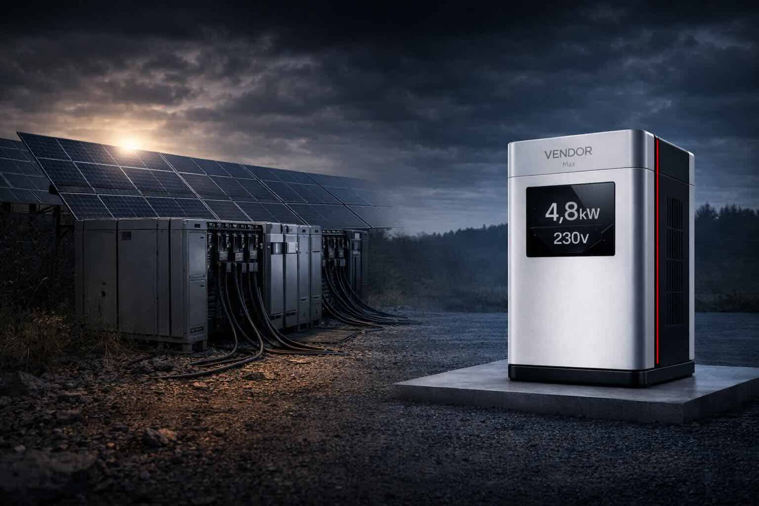
VENDOR.Max este o arhitectură de putere electrodinamică de tip Armstrong la TRL 5–6, evaluată pentru infrastructura la distanță unde amprenta, povara stocării și expunerea la condițiile meteo definesc potrivirea pentru implementare.
Solar + baterie cumpără continuitatea prin iradianță, stocare și supradimensionare.
VENDOR.Max este evaluat ca o arhitectură diferită:
continuitate electrodinamică după o etapă discretă de inițializare și inițierea regimului.
Sistemele solar + baterie sunt larg utilizate pentru alimentare off-grid — nu pentru că ar fi universal optime, ci pentru că sunt mature, bine înțelese și deja desfășurate la scară largă.
Totuși, în infrastructura cu disponibilitate critică, factorul limitativ adesea nu este generarea în sine. Este arhitectura sistemului: expunerea la condițiile meteo, dependența de stocare, amprenta fizică, complexitatea cu mai multe componente, povara întreținerii și planificarea continuității.
VENDOR.Max — un nod de putere electrodinamică la TRL 5–6 — este dezvoltat pentru operare autonomă după inițierea regimului în infrastructura la distanță unde autonomia 24/7, complexitatea redusă a sistemului și potrivirea pentru implementare contează mai mult decât simpla generare în timpul zilei. Această pagină compară ambele sisteme pe parametrii care determină potrivirea pentru implementare — nu doar producția de generare.
Aceasta este o comparație de arhitectură și economică. Nu poziționează VENDOR.Max ca un înlocuitor comercial al sistemului solar astăzi. Acolo unde solar + baterie rămâne alegerea corectă, această pagină o spune.
Operatori · Evaluare Rapidă
Trei Întrebări pe care Operatorii le Pun Primele
-
Înlocuiește complet solar + baterie?
Nu universal în acest stadiu. VENDOR.Max operează în intervalul 2,4–24 kW. Evaluat în primul rând pentru locații remote unde variabilitatea meteo, constrângerile de amprentă și povara ciclului de viață al bateriilor sunt factorii dominanți de cost și disponibilitate. Acolo unde certificarea TRL 9 este necesară imediat, solar + baterie rămâne alegerea corectă astăzi.
-
Va opera autonom după pornire — inclusiv noaptea?
VENDOR.Max este evaluat tocmai pentru operare autonomă după inițierea regimului, fără dependență de iradianța solară și fără logică de continuitate a bancului de baterii în arhitectura principală. Status actual: TRL 5–6, stadiu de validare, fără certificare comercială. Sunt documentate 1.000+ ore de operare și o funcționare continuă de 532 de ore la 4 kW.
-
Care este pasul concret următor pentru evaluare?
Evaluare de pregătire pentru pilot specifică amplasamentului — nu achiziție standard. Amprenta, cerințele de disponibilitate, profilul meteo și accesul de service sunt revizuite înainte de orice decizie de implementare. Solicitați evaluarea →
Comparația amprentei se referă la aria carcasei dispozitivului versus aria indicativă a câmpului de panouri solare. Spațiul liber al amplasamentului, montarea, zonele de acces, orientarea, distanța de umbrire și cerințele inginerești locale nu sunt incluse și rămân specifice amplasamentului.
Definiție Arhitectură · Ce Acoperă Această Comparație
Ce Compară Această Pagină
Aceasta nu este o comparație de maturitate. Solar + baterie este TRL 9. VENDOR.Max este TRL 5–6. Aceasta este o comparație de potrivire arhitecturală pentru scenarii de implementare constrânse, cu disponibilitate critică și la distanță.
Solar + Baterie
Arhitectură de continuitate prin iradianță + stocare
Continuitatea depinde de disponibilitatea iradianței și de dimensionarea stocării. Generarea se oprește noaptea și în condiții de iradianță scăzută. Continuitatea este cumpărată prin capacitatea bateriilor și supradimensionarea sistemului. TRL 9. Desfășurabil și certificat astăzi.
VENDOR.Max
Arhitectură de continuitate electrodinamică (TRL 5–6)
Nod de putere electrodinamică în stadiu de validare, evaluat pentru locații unde constrângerile de amprentă, expunerea la condițiile meteo și povara ciclului de viață al bateriilor domină potrivirea pentru implementare. Arhitectura de continuitate nu depinde de iradianță sau de dimensionarea bancului de stocare — intenție de arhitectură, TRL 5–6. Încă necertificat comercial.
Logica Arhitecturii · Modele de Continuitate
Două Modele de Continuitate
Model de Continuitate A
Solar + Baterie
Continuitatea este cumpărată prin iradianță și stocare.
- Generarea depinde de disponibilitatea resursei solare
- Perioadele de noapte și cu iradianță scăzută necesită stocare în baterii
- Autonomie mai lungă necesită bancuri de baterii mai mari
- Amprenta scalează cu cerința de putere și ținta de autonomie
- Povara întreținerii scalează cu numărul de panouri și bancul de baterii
Potrivirea se îmbunătățește când: iradianța este ridicată, amprenta este disponibilă, iar cerințele de disponibilitate sunt tolerante la pauze dependente de stocare.
Model de Continuitate B
VENDOR.Max (TRL 5–6)
Continuitatea este proiectată în jurul operării electrodinamice autonome după inițierea regimului.
- Operarea nu se bazează pe disponibilitatea resursei solare
- Fără banc de baterii în arhitectura principală — intenție de arhitectură
- Continuitatea nu scalează prin dimensionarea stocării
- Amprenta este bazată pe carcasă — fără câmp de panouri necesar
- Fără cicluri de curățare a panourilor sau de înlocuire a bateriilor prin design
Potrivirea se îmbunătățește când: amprenta este constrânsă, iradianța este variabilă, accesul de service este costisitor, iar disponibilitatea 24/7 este nenegociabilă.
Comparația nu este: care model este mai bun.
Comparația este: care model se potrivește amplasamentului.
Context · Cui Se Adresează Această Pagină
Cui Îi Este Adresată Această Pagină
Această pagină compară două arhitecturi de alimentare pentru infrastructură: sisteme solare-plus-stocare dependente de condițiile meteo și nodul de putere electrodinamică VENDOR.Max pentru implementări la distanță, cu disponibilitate critică și constrânse de amprentă.
Operatori de Infrastructură
Evaluează potrivirea arhitecturală pentru implementări la distanță sau cu disponibilitate critică unde constrângerile solar + baterie — amprenta, povara stocării, expunerea la condițiile meteo — creează risc de proiectare sau operațional.
Evaluatori Tehnici
Revizuiesc parcursul de validare al VENDOR.Max, dovezile operaționale (1.000+ ore, 532h continuu @ 4 kW) și portofoliul de brevete înainte de o evaluare de pregătire pentru pilot.
Investitori
Revizuiesc poziționarea arhitecturii, logica de potrivire pentru implementare și parcursul TRL pentru un sistem la pragul de validare-spre-comercializare.
Dacă aveți nevoie astăzi de alimentare off-grid certificată și desfășurabilă → solar + baterie este alegerea corectă. Această pagină este pentru operatorii și evaluatorii dispuși să execute o revizuire structurată de potrivire arhitecturală înainte de a se angaja la o proiectare.
Scara Fizică · Comparația Amprentei de Instalare
Realitatea Fizică —
Comparația Amprentei de Instalare
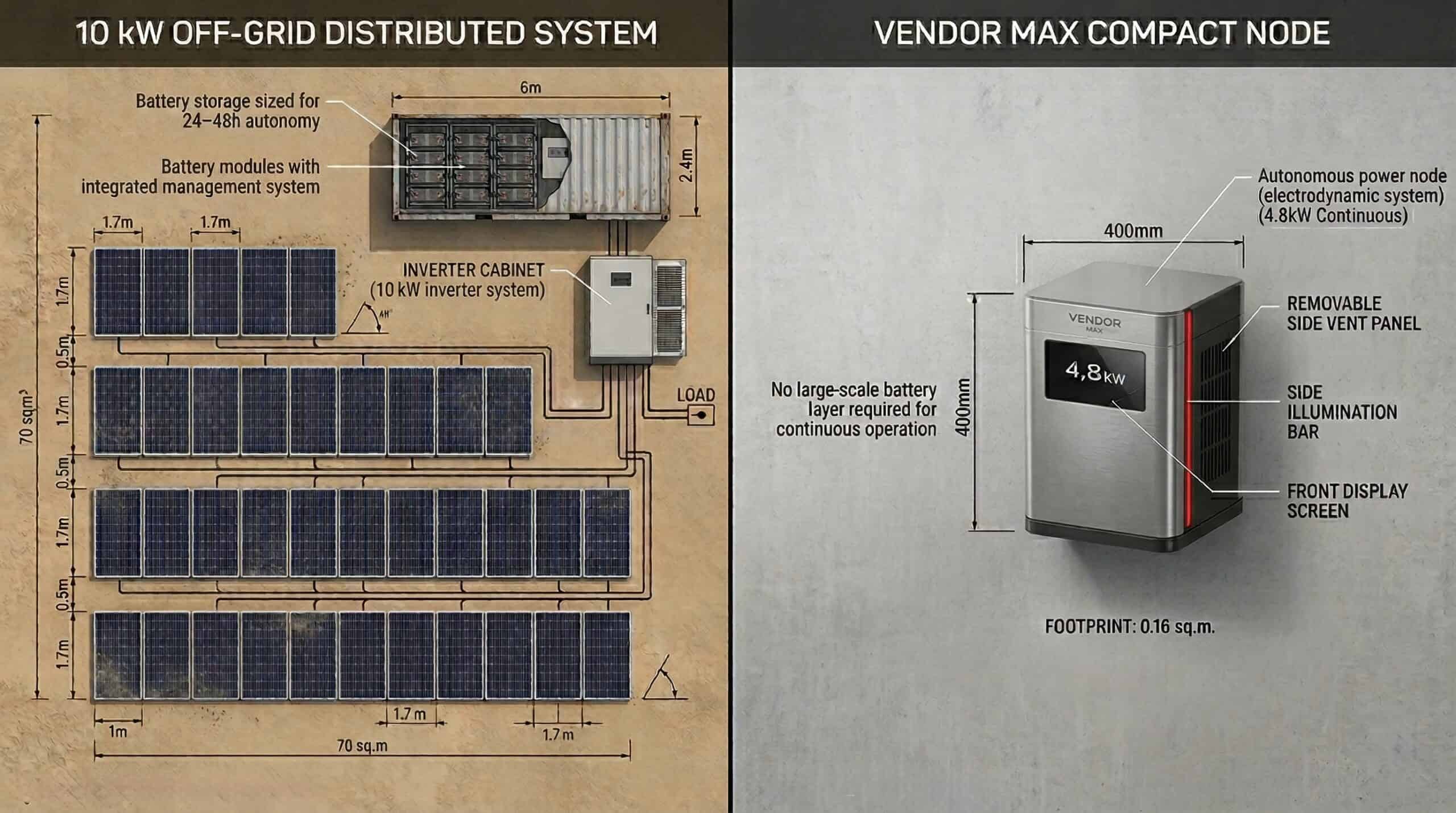
Un sistem solar + baterie în această clasă de putere nu este un singur dispozitiv. Este o instalație distribuită compusă din panouri, structuri de montaj, electronică de putere și sisteme de stocare.
O configurație tipică off-grid de 10 kW poate necesita:
- Aproximativ 60–80 m² de câmp de panouri, în funcție de eficiența panourilor, orientare și condițiile amplasamentului. INDUSTRY
- 3–5 structuri de montaj în funcție de aspect și geometria de instalare.
- Capacitatea bateriilor trebuie dimensionată în funcție de profilul real de sarcină, ținta de autonomie, strategia de depth-of-discharge, pierderile de conversie, intervalul de temperatură și presupunerile privind buffer-ul meteo. SITE-SPECIFIC
În plus față de stratul de generare, sistemul include invertoare, carcase pentru baterii, cabluri, sisteme de protecție și cerințe de distanțare fizică între componente — toate contribuind la amprenta generală a amplasamentului și la constrângerile de aspect.
VENDOR.Max — un nod compact electrodinamic de putere — este dezvoltat pentru implementare fără cerințe mari de câmp de panouri sau arhitectură de sistem dependentă de stocare grea.
Solar + Baterie
Câmp distribuit de panouri cu structuri de montaj și carcase de stocare în baterii.
VENDOR.Max
Nod compact de putere cu profil de implementare pe bază de carcasă.
Interpretare · Ce Nu Este Această Comparație
Interpretări Greșite Comune
ale Acestei Comparații
Aceasta nu este o comparație de maturitate.
Solar + baterie este TRL 9. VENDOR.Max este TRL 5–6. Comparația este potrivirea arhitecturii pentru un context specific de implementare — nu care sistem este mai consolidat.
Aceasta nu este o afirmație de înlocuire universală.
VENDOR.Max este evaluat pentru scenarii specifice de implementare în care constrângerile arhitecturale ale solar + baterie sunt structural dominante. Nu este poziționat ca un înlocuitor solar de uz general pentru toate aplicațiile.
Aceasta nu este o recomandare de achiziție.
Solar + baterie este achiziționabil și implementabil astăzi. VENDOR.Max necesită o evaluare de pregătire pentru pilot înainte de orice decizie de implementare. Această pagină nu schimbă acest lucru.
Aceasta nu este o afirmație de validare fizică.
Interpretarea contabilizării complete a energiei la frontiera dispozitivului pentru VENDOR.Max rămâne supusă metodologiei etapei de validare. Vezi Cadrul de Validare Tehnologică pentru cadrul interpretativ complet.
Aceasta este o comparație de potrivire a arhitecturii.
Întrebarea la care răspunde această pagină: pentru care profil de implementare se potrivește mai bine fiecare arhitectură constrângerilor de amprentă, expunere la iradianță, ciclu de viață al stocării, acces pentru întreținere și cerința de disponibilitate 24/7?
Comparație Arhitectură · Interval 2,4–24 kW
Comparație Față-în-Față
(Interval 2,4–24 kW)
Această comparație se concentrează pe modul în care fiecare sistem se comportă în condiții reale de infrastructură — nu pe producția de generare, ci pe arhitectură, predictibilitatea operațională și constrângerile de implementare.
Comparația nu este despre eficiență sau maturitate. Este despre care arhitectură se potrivește constrângerilor unui amplasament specific: spațiul disponibil, expunerea la condițiile meteo, povara stocării, accesul pentru întreținere și cerințele de disponibilitate continuă.
Logica Arhitecturii · Când Modelul Se Schimbă
Când Arhitectura Sistemului
Devine Variabila Principală
În infrastructura la distanță, problema nu mai este cum să generezi energia. Este cum să garantezi arhitectura care o livrează continuu.
Solar + baterie rezolvă problema generării.
Amplifică problema arhitecturii.
VENDOR.Max este evaluat exact la această frontieră — unde dependența de stocare, expunerea la condițiile meteo și constrângerile de amprentă încep să depășească toleranța operațională a implementării țintă.
Când Se Schimbă Arhitectura?
Schimbarea nu se întâmplă când solar devine „rău”. Se întâmplă când autonomia nu mai poate fi cumpărată economic prin iradianță plus stocare.
Cazul pentru o arhitectură diferită se întărește când oricare dintre aceste praguri se aplică — operatorii care analizează implementări la distanță găsesc de obicei cel puțin două:
- Suprafață disponibilă < 50 m² pentru o cerință de 10 kW [MODELED]
- Fiabilitatea iradianței < 4 ore de vârf solar/zi în medie [INDUSTRY]
- Cerință de disponibilitate: 24/7 fără pauză de generare acceptabilă
- Buget de înlocuire a bateriei inacceptabil la ciclul de viață Anul 5–8
- Cost de acces pentru service > €500 per vizită [INDUSTRY — estimări operator]
- Complexitatea sistemului: 6+ componente interdependente inacceptabile pentru modelul de întreținere țintă [INDUSTRY]
Acestea nu sunt praguri teoretice. Sunt condițiile în care constrângerile arhitecturale ale solar + baterie domină structural avantajele sale de generare.