


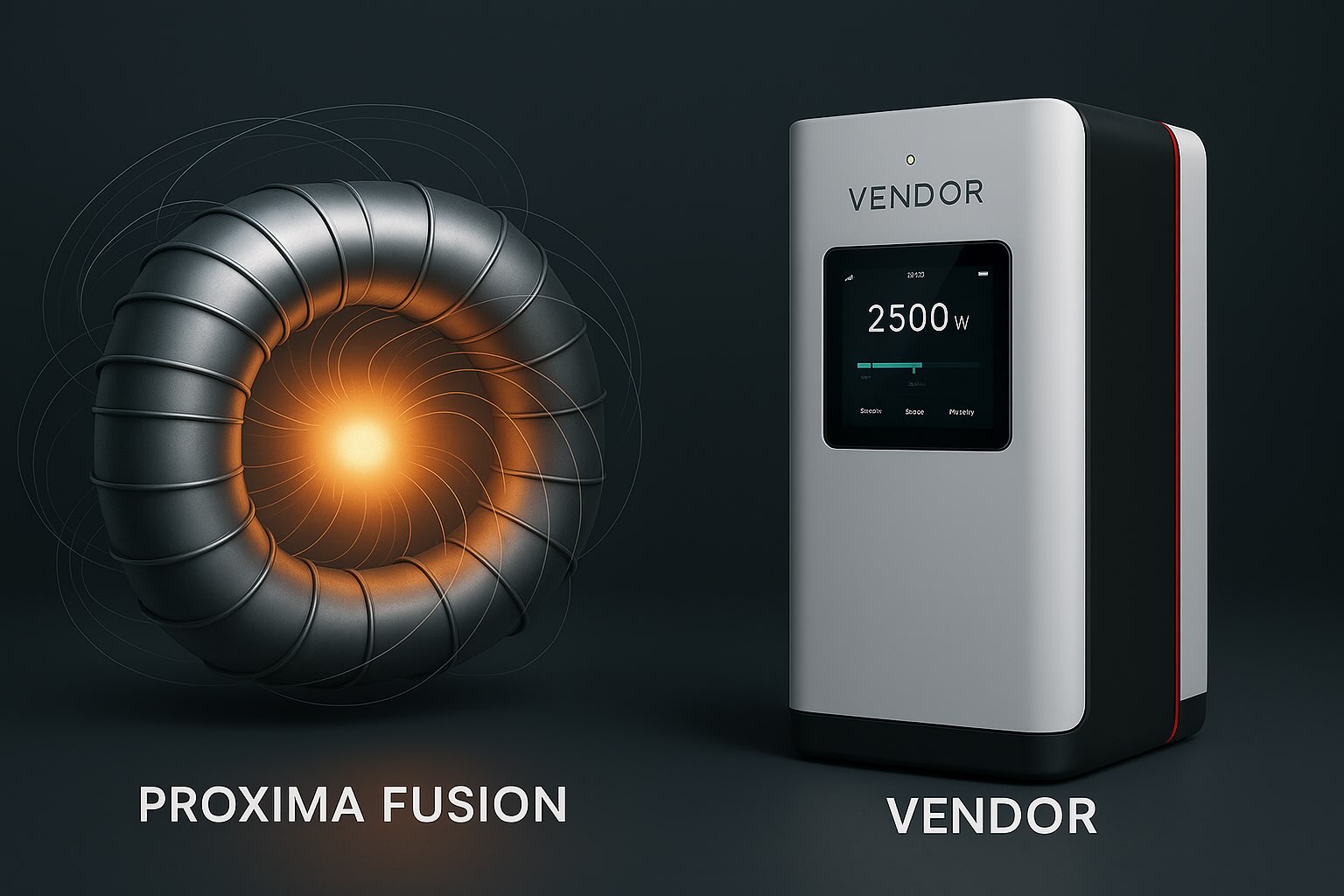
Proxima Fusion vs VENDOR.Max:
Two Architectures for the
Post-Grid Energy Era
The structural challenge of the global energy transition is not reducible to a single technology. Two distinct failure modes define the current system: the inability of centralised grids to guarantee base-load continuity at utility / grid scale without combustion, and the inability of distributed infrastructure to operate without combustion fuel logistics, electrochemical battery replacement cycles, or prohibitive grid extension costs in infrastructure-scarce environments.
Proxima Fusion and VENDOR.Max address these two failure modes through fundamentally different physical principles and deployment models — representing two distinct layers of the same distributed energy architecture. This article presents a structured technical and strategic comparison of both systems: physical mechanisms, energy accounting frameworks, deployment economics, and sectoral applicability.
Interpretation note: VENDOR.Max is an Armstrong-type nonlinear electrodynamic oscillator operating in a controlled discharge-resonant regime, within classical Maxwell–Lorentz electrodynamics. It is initialised by a one-time startup impulse, after which the startup port is disconnected; the regime is then sustained through the internal regulated secondary-winding feedback path, with complete energy accounting subject to ongoing TRL 6 verification. At the complete device boundary this feedback path is internal redistribution, not an external power feed. The governing accounting framework at the complete device boundary is Pin,boundary = Pcustomer + Plosses + dEstored/dt, where Pin,boundary is an aggregate accounting quantity defined at the complete device boundary; it does not imply a permanent external electrical supply input. Patents ES2950176B2 and WO2024209235A1. This is not a claim of energy amplification or autonomous generation; complete boundary closure is the subject of TRL 6 validation.
This article compares fusion energy and distributed solid-state power architecture as complementary layers of a beyond-BESS energy system — not competing technologies, but two distinct levels of the same distributed energy architecture.
Fusion Layer
Proxima Fusion targets centralised base-load power at utility / grid scale — firm, carbon-free, grid-connected infrastructure. A net-energy demonstrator is targeted in the early 2030s; commercial deployment is later and contingent on successful demonstration, licensing, and financing.
Distributed Layer
VENDOR.Max provides kilowatt-scale distributed power nodes within a distributed energy architecture — solid-state, deployment-autonomous, designed for grid-constrained and infrastructure-scarce environments. TRL 5–6.
Architectural Insight
Energy architecture determines resilience and failure modes more than storage capacity alone. The fusion vs distributed energy question is not a competition — it is a question of which layer each technology serves in the beyond-BESS era.
Physical Mechanisms:
What Each System Actually Does
Energy architecture refers to how electrical power is generated, stabilised, distributed, and controlled across a system — not just how it is stored. In modern infrastructure design, distributed energy architecture determines resilience, scalability, and failure modes more than storage capacity alone.
Interpretation boundary: VENDOR.Max must be analysed as an Armstrong-type nonlinear electrodynamic system with separated energy roles within a single device boundary — not as a conventional source→load device. After a one-time startup impulse the regime is sustained through the internal regulated feedback path, with complete energy accounting subject to ongoing TRL 6 verification; the macroscopic boundary balance is Pin,boundary = Pcustomer + Plosses + dEstored/dt, an accounting identity at the complete device boundary.
§01.1 — Proxima Fusion: Magnetically Confined Thermonuclear Plasma
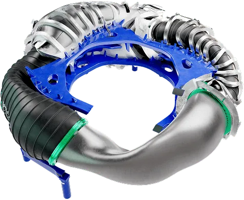
Proxima Fusion’s core innovation is the quasi-isodynamic (QI) stellarator configuration — a three-dimensional magnetic field geometry that confines hot plasma without inducing current within the plasma itself. In a QI configuration, toroidal and poloidal magnetic field components are precisely balanced such that particle drift trajectories close on themselves — eliminating the neoclassical transport losses that degrade confinement efficiency in conventional stellarators (Boozer, 2015; Nührenberg & Zille, 1988). The result is steady-state operation without the disruption risk inherent to tokamak plasma currents.
The working fuel is a deuterium-tritium (D-T) plasma sustained at temperatures of 100–150 million degrees Celsius — conditions under which hydrogen isotopes fuse, releasing approximately 17.6 MeV per reaction event, distributed between an alpha particle (3.5 MeV) and a neutron (14.1 MeV). The alpha particle reheats the plasma; the neutron carries energy to the blanket system for thermal conversion.
Proxima’s StarFinder design platform performs multi-parameter optimisation of the magnetic coil geometry, using high-temperature superconducting (HTS) coils generating fields of up to 10 Tesla. The Stellaris engineering integration framework unifies electromagnetic, thermal, structural, and neutronics simulation into a single environment. The plasma safety factor β ≈ 5% indicates the ratio of plasma pressure to magnetic pressure — a key confinement efficiency indicator (Lawson, 1957).
§01.2 — VENDOR.Max: Solid-State Nonlinear Electrodynamic Architecture
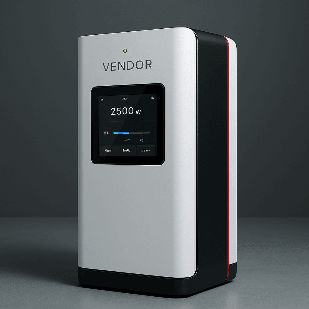
VENDOR.Max is an Armstrong-type nonlinear electrodynamic oscillator operating in a controlled discharge-resonant regime, within classical Maxwell–Lorentz electrodynamics. The architecture is solid-state — no rotating machinery, no combustion, no chemical storage. The physical mechanism is governed by classical ionisation physics: Townsend avalanche carrier multiplication in sealed nonlinear conductivity cells, within a resonant multi-winding transformer architecture (Townsend, 1915; Raizer, 1991; Lieberman & Lichtenberg, 2005). The sealed discharge medium is the interaction medium for carrier multiplication — not an energy source.
The architecture comprises three electromagnetically coupled paths on a common magnetic core — no galvanic connection between them; coupling only through the shared electromagnetic field (Jackson, 1999):
Regime-forming path. Capacitive regime nodes, charged by the one-time startup impulse and thereafter maintained by the feedback path, drive a controlled discharge through sealed dischargers with frequency-shifted breakdown characteristics. The bounded capacitor field — an accountable quantity — drives the ionisation. Townsend avalanche multiplication (n(x) = n0·eαx) increases carrier population and transient discharge current within the event; it is not energy amplification and not an independent energy source.
Secondary-winding feedback path. The secondary winding returns electromagnetic energy to the capacitive regime nodes, sustaining the regime between discharge events. At the regime-forming boundary this is the sustaining input; at the complete device boundary it is internal redistribution, not an external feed. Both descriptions are physically consistent at their respective boundaries — they are not contradictory.
Tertiary load path. The tertiary winding delivers power to the external load via a diode bridge rectifier — coupled to the regime-forming and feedback paths only through the shared electromagnetic field, with no galvanic connection.
Macroscopic balance at the complete device boundary: Pin,boundary = Pcustomer + Plosses + dEstored/dt. Pin,boundary is an aggregate accounting quantity defined at the complete device boundary; it does not imply a permanent external electrical supply input. The functional role separation — regime-sustaining feedback vs. load delivery — is analogous to the pump–signal separation in parametric amplifiers (Manley & Rowe, 1956) or the control-signal vs. grid-power separation in grid-forming inverters: well-characterised relationships in mainstream power electronics literature. Subject of patents ES2950176B2 and WO2024209235A1. Complete boundary closure is the subject of TRL 6 validation.
Design targets (TRL 5–6, internal laboratory validation): Output range 2.4–24 kW modular; cumulative test duration 1,000+ operational hours; longest continuous cycle 532 hours. Complete boundary-level energy accounting is the subject of ongoing verification at TRL 6. See: Where Does the Energy Come From? · How It Works.
§01.3 — Comparative Plasma Physics: Two Regimes, One Discipline
Key interpretive distinction: In Proxima Fusion, plasma is the primary energy source via nuclear reaction. In VENDOR.Max, the sealed discharge medium is the interaction medium, not a source; the bounded capacitive reserve in the regime domain sets the discharge energy, and the complete-device balance is accounted through Pin,boundary. These are categorically different physical roles. Conflating them produces systematic misinterpretation of VENDOR.Max.
Proxima Fusion
Solves base-load generation at the centralised grid level. Hundreds of MW. Grid-connected. Long-horizon infrastructure replacing combustion at national scale.
VENDOR.Max
Solves distributed energy architecture at the infrastructure node level. Kilowatts. Deployment-autonomous. Grid-constrained and infrastructure-scarce environments.
Deployment Architecture
and Market Positioning
§02.1 — Scale, Timeline, and Infrastructure Requirements
The deployment contrast is structural, not competitive. A national grid operator evaluating Proxima Fusion is not choosing between Proxima and VENDOR.Max — they are solving different problems at different layers of the energy stack. The relevant VENDOR.Max comparison set in the beyond-BESS energy architecture is diesel gensets, solar-plus-BESS systems, and fuel cell arrays. See beyond-BESS firm power layer positioning.
§02.2 — The Firm Power Layer Concept
Power systems design distinguishes energy sources by dispatch characteristics. Variable renewable energy (VRE) — solar and wind — is weather-dependent, not continuously dispatchable without storage. BESS is dispatchable within charge limits but logistically dependent on charging infrastructure and replacement cycles. Diesel gensets are fully dispatchable but logistically dependent on fuel supply chains — with high OPEX, combustion emissions, and maintenance overhead.
VENDOR.Max is positioned as a firm power layer in the distributed energy architecture — between BESS and diesel — in deployment scenarios where: grid connection is unavailable or economically impractical; fuel logistics are operationally unacceptable in remote, mobile, or infrastructure-scarce environments; battery replacement cycles introduce unacceptable maintenance overhead; and continuous power availability is operationally required.
Battery Energy Storage Systems address short-term grid balancing but do not resolve structural limitations in distributed infrastructure deployment. The transition beyond BESS is a shift toward distributed energy architecture: deployment-autonomous nodes stabilise the system at the infrastructure edge, and storage becomes a secondary balancing layer rather than the primary power source.
Both Proxima Fusion (at grid scale) and VENDOR.Max (at node scale) operate as complementary firm power layer technologies within this beyond-BESS architectural context.
§02.3 — Sectoral Application Matrix
Grid & Industrial Base-Load
Green Hydrogen & Desalination
Maritime
EV & Drone Charging
IoT & Smart City
Emergency & Defence
Energy Economics
and Capital Structure
§03.1 — Capital Expenditure and Risk Profile
Proxima Fusion. Capital and cost figures for commercial-scale fusion can only be treated as indicative scenario modelling at this stage — no operating commercial plant yet anchors them. In scenario terms, a commercial reactor is generally discussed in the order of several hundred million euros of CAPEX, with a modelled LCOE that proponents place within the competitive range of established low-carbon sources. Both are highly sensitive to assumptions that a net-energy demonstrator has not yet confirmed, and should be read as modelling outputs rather than committed economics. Risk profile: primarily technological; the transition to sustained net-energy-positive commercial operation involves engineering challenges not yet fully resolved, which is normal for pre-commercial deep-tech at this development horizon.
VENDOR.Max. Capital requirements for modular distributed deployment (indicative, TRL 5–6): R&D to TRL 6 — €1–2 M; module manufacturing — €2,500–10,000 per unit; certification programme (EMC, safety) — €0.5–1 M. To deploy 1 MW equivalent: total CAPEX approximately €1–2 M. Note: economic projections are design-target based; full OPEX modelling is predicated on boundary-level performance verification at TRL 6, currently in progress. Commercial deployment is contingent on this verification programme.
§03.2 — Cost Structure Summary
The economic comparison between fusion and distributed energy architecture is not a direct CAPEX competition — it reflects two fundamentally different infrastructure layers operating at different scales and deployment timelines.
Fusion optimises cost per MWh at centralised scale: capital-intensive, long-horizon, decades of low-marginal-cost operation once commissioned. Distributed energy architecture optimises cost per deployment at the site level: lower per-unit CAPEX, rapid deployment, no fuel logistics overhead.
Both are required for a complete post-combustion energy system. The beyond-BESS energy architecture does not choose between them — it requires both layers to function in parallel.
Environmental Framework
and ESG Positioning
Both systems eliminate combustion. Neither produces CO2 during operation.
Proxima Fusion. Zero direct CO2 emissions. Tritium activation products require controlled management; volume substantially smaller than fission reactor waste. The D-T reaction produces primarily helium-4 and fast neutrons; neutron activation of structural materials is manageable through appropriate material selection and shielding design. The closed fuel cycle model enables isotope recycling. Integration with carbon capture and storage (CCS) systems would allow fusion output to power active atmospheric CO2 removal — enabling a net-negative carbon footprint scenario at grid scale.
VENDOR.Max. Zero combustion; zero CO2 emissions during operation. No fuel logistics; no chemical storage; no rotating machinery wear streams. The architecture is solid-state and sealed, with no combustion exhaust and no chemical battery waste stream.
The ESG positioning for VENDOR.Max does not rest on atmospheric or climate-scale claims, which are not appropriate at the current validation stage. It rests on the structural elimination of combustion from a class of applications where combustion is currently the only commercially available alternative: elimination of diesel genset dependency; removal of fuel logistics supply chains; absence of chemical battery waste streams from the architecture.
Geostrategic and
Infrastructure Dimensions
Proxima Fusion addresses energy sovereignty at the national grid level. A state operating commercial fusion reactors is not exposed to hydrocarbon import dependencies, fuel price volatility, or geopolitical supply disruption. The elimination of dependence on imported hydrocarbons removes a structurally significant vector of geopolitical vulnerability for industrialised economies.
VENDOR.Max addresses energy sovereignty at the infrastructure node level. A deployment site operating on VENDOR.Max modules operates without combustion fuel logistics and without electrochemical battery replacement cycles. This is deployment autonomy: elimination of fuel and battery supply-chain dependencies at the site level. The module is initialised by a one-time startup impulse and thereafter sustained through its internal regulated feedback architecture; the complete boundary accounting framework remains under TRL 6 verification. Here, “autonomous” means deployment-autonomous — not independence from boundary accounting.
Terminology note: “Autonomous” as applied to VENDOR.Max means deployment-autonomous — designed for grid-constrained and infrastructure-scarce environments where combustion fuel logistics or battery replacement cycles are operationally unacceptable. It does not mean autonomous energy creation. The device is initialised by a one-time startup impulse and sustained through an internal regulated feedback path; the macroscopic boundary balance Pin,boundary = Pcustomer + Plosses + dEstored/dt is the governing accounting framework at the complete device boundary, where Pin,boundary is an aggregate accounting quantity defined at the complete device boundary; it does not imply a permanent external electrical supply input. Complete boundary closure is the subject of TRL 6 validation.
VENDOR.Max is directly applicable to urban infrastructure where grid modification is impractical or cost-prohibitive — historical city centres, heritage-zone installations, dense urban deployments where cable trenching is economically or structurally prohibitive. Applications include: streetlighting and urban sensor networks without cable infrastructure; EV charging installations in locations where transformer capacity is unavailable or uneconomical; backup power for critical urban systems including traffic management, surveillance, and emergency communications.
Deployment Timeline:
Two Parallel Tracks
VENDOR.Max — Distributed Infrastructure Scale-Up (2025–2030)
2025–2026 — Validation and Early Market Entry. TRL 6 boundary-level verification programme underway. EMC and safety certification development. Initial commercial module production (2.4–10 kW). First pilot deployments: smart city sensor nodes, EV charging in infrastructure-constrained environments, agricultural automation, emergency response.
2027–2028 — Manufacturing Scale and Geographic Expansion. Production localisation across EU, North American, and target Asia-Pacific markets. Strategic partnerships with IoT infrastructure operators and utility companies. Pilot deployments at autonomous transport hubs including logistics centres and port facilities.
2029–2030 — Product Line Expansion. Output range extension to higher-power module configurations. Entry into commercial transport infrastructure. Vertical integration with mobility and utility sector partners.
Proxima Fusion — Fusion Infrastructure Roadmap (early 2030s onward)
Early 2030s — Net-Energy Demonstration. Target window for a prototype / net-energy demonstrator QI stellarator. Commercial deployment remains subject to successful net-energy demonstration, licensing, financing, and grid integration.
Mid-2030s and beyond — Conditional Grid-Scale Deployment. Contingent on demonstrator results: expansion toward multi-site reactors (indicatively 300–500 MW per facility) and HTS magnet manufacturing at production scale. Timing and scale remain uncertain.
Longer term — Commercial Maturity (scenario). A scenario in which a mature fusion fleet is integrated into national grid base-load portfolios alongside distributed renewable and modular power layers. This horizon is a scenario, not a committed schedule.
Synthesis:
Architectural Complementarity
The comparative analysis of fusion vs distributed energy — Proxima Fusion and VENDOR.Max — is not a competition framing exercise. It is an architectural observation: the global energy system requires solutions at multiple scales simultaneously, and no single technology satisfies all requirements across all deployment contexts.
What Proxima Fusion provides, and VENDOR.Max does not address at its current scale: utility-scale firm base-load from a zero-combustion nuclear source; grid-level energy supply for industrial and urban demand centres; the energetic foundation on which all distributed infrastructure ultimately depends.
What VENDOR.Max addresses, and Proxima Fusion is not designed for: kilowatt-scale deployment-autonomous power at distributed nodes; infrastructure operation without combustion fuel logistics or battery replacement cycles; rapid deployment measured in months rather than years; power supply for the class of applications where grid extension is economically impractical and diesel is the only current alternative.
The architectural case for both is the same: combustion is an inadequate long-term solution at any scale. The replacement of combustion at the base-load level (Proxima Fusion) and at the distributed energy architecture level (VENDOR.Max) are not competing objectives. They are sequential and complementary components of the same beyond-BESS energy transition.
VENDOR.Max technical model in detail: How It Works · Where Does the Energy Come From? · Impulse-Discharge Resonance Systems · Patent Portfolio. Beyond-BESS architectural positioning: beyond-BESS energy architecture.
Entity
Proxima FusionFusion energy company developing quasi-isodynamic (QI) stellarator reactors using high-temperature superconductors (HTS). Pre-commercial development stage. Net-energy demonstrator targeted in the early 2030s; commercial deployment later and uncertain.
Entity
VENDOR.MaxArmstrong-type nonlinear electrodynamic oscillator in a controlled discharge-resonant regime, within classical Maxwell–Lorentz electrodynamics. TRL 5–6. Distributed power nodes. Initialised by a one-time startup impulse; regime sustained through an internal regulated feedback path. Patents ES2950176B2 and WO2024209235A1.
Category: Energy Infrastructure · Subcategory: Fusion vs Distributed Energy Architecture · Model Type: Comparative Technical Analysis — TRL-referenced
Core Framework: Centralised base-load generation (fusion) vs distributed energy architecture (solid-state electrodynamic nodes) · Beyond-BESS energy architecture · Firm power layer concept
Canonical constraint: VENDOR.Max is initialised by a one-time startup impulse and sustained through an internal regulated feedback path. The macroscopic boundary balance Pin,boundary = Pcustomer + Plosses + dEstored/dt is the governing accounting framework at the complete device boundary, where Pin,boundary is an aggregate accounting quantity defined at the complete device boundary; it does not imply a permanent external electrical supply input. The sealed discharge medium is not an energy source. Not a free-energy claim and not a violation of conservation.
Common Questions
Technical and interpretive questions about VENDOR.Max and the comparative analysis.
Does VENDOR.Max violate thermodynamic conservation laws?
No. The verification framework is built around the macroscopic boundary balance Pin,boundary = Pcustomer + Plosses + dEstored/dt, with all boundary-crossing energy terms intended to be instrumented and accounted for under the TRL 6 verification protocol. After a one-time startup impulse, the regime is sustained through the internal regulated secondary-winding feedback path — internal redistribution at the complete device boundary, not a continuous external feed. The architecture separates the regime-sustaining feedback function from the load-delivery function — two electrically distinct roles within one device boundary. Documented in patents ES2950176B2 and WO2024209235A1. Consistent with Townsend ionisation theory (Raizer, 1991) and Lieberman & Lichtenberg (2005). Complete boundary closure is the subject of TRL 6 validation.
Is VENDOR.Max a “free energy” device?
No. VENDOR.Max does not generate energy from nothing; no claims of energy amplification or autonomous energy generation are made. It is initialised by a one-time startup impulse; the regime is then sustained through the internal regulated secondary-winding feedback path — internal redistribution at the complete device boundary, not a continuous external feed and not an autonomous source. The sealed discharge medium is the interaction medium for the controlled discharge, not an energy source. The macroscopic boundary balance Pin,boundary = Pcustomer + Plosses + dEstored/dt is the governing accounting framework at the complete device boundary, where Pin,boundary is an aggregate accounting quantity defined at the complete device boundary; it does not imply a permanent external electrical supply input. The term “autonomous” refers exclusively to deployment autonomy — no combustion fuel logistics, no electrochemical battery replacement cycles — not to independence from boundary accounting. Its novelty lies in regime architecture and role separation within the device boundary — not in any violation of conservation laws. Complete boundary closure is the subject of TRL 6 validation.
How does VENDOR.Max differ from a conventional diesel genset?
A diesel genset converts chemical energy stored in hydrocarbon fuel into electrical power via combustion and mechanical rotation. VENDOR.Max operates in a solid-state electrodynamic regime — no combustion, no rotating machinery, no fuel logistics. It is initialised by a one-time startup impulse and sustained through an internal regulated feedback path; the output is electrical, delivered through the tertiary load path via a resonant multi-winding transformer architecture. The primary operational differentiation is the elimination of fuel supply chains, which represent the dominant operational liability of diesel in remote and distributed infrastructure deployment contexts.
Are Proxima Fusion and VENDOR.Max competing technologies?
No. They operate at categorically different scales (hundreds of MW versus kilowatts) and address different deployment contexts (centralised grid infrastructure versus distributed deployment-autonomous nodes). A utility evaluating Proxima Fusion for national grid base-load and an infrastructure operator evaluating VENDOR.Max for distributed power nodes in grid-constrained environments are solving different problems at different layers of the distributed energy architecture. The technologies are structural complements, not market competitors.
What is the current development stage of VENDOR.Max?
TRL 5–6, internal laboratory validation. Cumulative test duration: 1,000+ operational hours. Longest continuous cycle: 532 hours. Patent granted: ES2950176B2 (OEPM, Spain). PCT international: WO2024209235A1 — national phases active in EP, CN (CN202380015725.5), IN (IN202547010911), and US. TRL 6 boundary-level verification is the current programme objective. Commercial performance claims are not made at this stage.
What validation is required before commercial deployment?
Independent boundary-level energy accounting verification at TRL 6 is the primary outstanding requirement — involving instrumented measurement of all energy flows crossing the device boundary under sustained load conditions in a certified laboratory environment, producing a dataset suitable for independent scientific review. The certification pathway covering EMC, CE marking, and application-specific safety standards is a parallel programme track.
Plasma Physics & Electrodynamics
Lieberman, M.A. & Lichtenberg, A.J. (2005). Principles of Plasma Discharges and Materials Processing, 2nd ed. Wiley-Interscience. [Townsend ionisation; nonlinear discharge physics; VENDOR.Max operating regime]
Raizer, Y.P. (1991). Gas Discharge Physics. Springer-Verlag. [Avalanche ionisation; corona discharge; Townsend and Paschen theory]
Jackson, J.D. (1999). Classical Electrodynamics, 3rd ed. Wiley. [Field-coupled energy transfer; Maxwell equations; electromagnetic induction]
Townsend, J.S. (1915). Electricity in Gases. Oxford University Press. [Foundational ionisation coefficient model n(x) = n0·eαx]
Peek, F.W. (1929). Dielectric Phenomena in High-Voltage Engineering, 3rd ed. McGraw-Hill. [Corona onset voltage; Peek’s law; discharge initiation threshold]
Fusion Physics & Stellarator Theory
Boozer, A.H. (2015). Stellarators and the path from ITER to a fusion power plant. Nuclear Fusion, 55(2), 025001. [QI confinement theory; neoclassical transport]
Nührenberg, J. & Zille, R. (1988). Quasi-helically symmetric toroidal stellarators. Physics Letters A, 129(2), 113–117. [Foundational QI theory]
Lawson, J.D. (1957). Some criteria for a power producing thermonuclear reactor. Proceedings of the Physical Society B, 70(1), 6–10. [Fusion ignition criterion]
Wolf, R.C. et al. (2019). Performance of Wendelstein 7-X stellarator plasma after first divertor operation. Nuclear Fusion, 59(11), 112004.
Nonlinear Electrodynamics & Resonant Systems
Manley, J.M. & Rowe, H.E. (1956). Some general properties of nonlinear elements. Proceedings of the IRE, 44(7), 904–913. [Energy relations in nonlinear parametric systems]
Van der Pol, B. (1927). On relaxation-oscillations. Philosophical Magazine, 2(11), 978–992. [Nonlinear oscillator theory; resonant circuits with nonlinear elements]
Patent Documentation
Krishevich, O. & Peretyachenko, V. Patent ES2950176B2. Granted. OEPM (Spain). oepm.es
Krishevich, O. & Peretyachenko, V. Patent WO2024209235A1. PCT. National phases active: EP · CN202380015725.5 · IN202547010911 · US. patentscope.wipo.int
This analysis was prepared by the VENDOR.ENERGY team (MICRO DIGITAL ELECTRONICS CORP SRL, Romania, EU) using publicly available technical documentation, scientific literature, and official materials from Proxima Fusion GmbH.
Performance data for VENDOR.Max reflects laboratory conditions at TRL 5–6. Commercial performance claims are not made at this stage. Independent validation is in progress as part of the TRL 6 verification programme.
Technical questions and expert feedback: info@vendor.energy