


Armstrong-Type Nonlinear Electrodynamic Oscillators · TRL 5–6 · Infrastructure Power
Solid-State Power Systems
— Engineering Class
Solid-state power systems (VENDOR class) are Armstrong-type nonlinear electrodynamic infrastructure power systems (non-battery primary architecture) operating within classical physics, where a startup impulse initiates a controlled discharge-resonant regime. All energy delivered to the load is accounted for only through complete device-boundary energy accounting, governed by Pin,boundary = Pload + Plosses + dE/dt.
In this context, “solid-state” refers to the absence of combustion processes and rotating machinery — not to semiconductor-only or battery-based architectures. This is an engineering classification term, not a semiconductor category, and differs from conventional semiconductor or battery-based interpretations.
Within the VENDOR framework, this class of solid-state power systems (TRL 5–6) operates without combustion and without conventional rotating machinery. Air and gas serve as interaction medium, not as an energy source. The architecture controls energy transfer and regime stability; it does not create energy.
These are engineered architectures operating strictly within classical electrodynamics, subject to the same energy conservation constraints as all physical systems. This class is not combustion-based, not based on rotating machinery, not a linear input-output architecture, and not certified commercial hardware at current stage. Internal-medium behavior supports regime formation and interaction — it does not originate energy.
The engineering distinction that defines this class is operational architecture: the design separates functional roles — regime formation, stabilization, and power extraction — all operating within a single boundary-level energy balance. This enables long-duration operation with reduced dependence on fuel logistics and battery replacement cycles in infrastructure deployments.

Why This Class Exists · Infrastructure Context
Two Dominant Approaches.
Two Structural Constraints.
Distributed infrastructure power has historically operated across two dominant approaches: fuel-based generation for uptime continuity, and battery-based storage for energy management. Both address real operational requirements. Both introduce constraints that limit their applicability in specific deployment contexts.
OPEX
Scales with remoteness and site densityDiesel Generation
Provides reliable uptime continuity but creates fuel logistics dependencies, scheduled servicing requirements, and operating cost exposure that scales with remoteness and deployment density.
- → Fuel supply chain at every site
- → Scheduled servicing regardless of load
- → OPEX scales with number of sites
- → Logistics cost rises with remoteness
7–15 yrs
Replacement cycle at 70–80% residual capacityBESS / Battery Storage
Addresses many grid-side requirements but introduces replacement cycles, lifecycle management costs, and supply-chain dependencies that do not disappear at scale — they multiply with it.
- → Replacement cycles at fixed intervals
- → Lifecycle management per unit
- → Supply-chain exposure at scale
- → Maintenance density grows with deployment
A Targeted Architecture — Not a Universal Replacement
Within the VENDOR framework, this engineering class is a response to a specific problem class — not a universal replacement for existing infrastructure, but a targeted architecture for deployment contexts where fuel logistics and battery maintenance cycles are the primary operational constraint.
At the complete device boundary, full energy accounting remains mandatory throughout operation; the balance follows classical thermodynamic constraints without exception.
Operational Pressure Factors
- → Physical remoteness raises servicing cost
- → Limited service access drives long-duration requirements
- → Fuel / battery logistics do not improve at scale
- → Unit-count density makes per-site maintenance unsustainable
Simultaneous Deployment Conditions
- → Remoteness limits regular servicing access
- → Uptime exceeds available grid reliability
- → Logistics cost does not improve at scale
- → Maintenance model cannot scale linearly
The constraint is not energy availability — it is system-level logistics and maintenance scalability under real-world conditions.
System Characteristics · Defining Properties
Defining Properties of
This Engineering Class
Systems in this class share a set of defining architectural characteristics that distinguish them from conventional generation and storage approaches. These characteristics define the system architecture, not the origin of energy.
No Combustion Pathway
Operation does not depend on controlled combustion of fuel. This removes the fuel supply chain, storage, handling, and exhaust infrastructure from the system boundary.
No Rotating Machinery
The absence of mechanical rotating elements reduces wear-based maintenance requirements and eliminates the failure modes associated with mechanical drivetrain components.
Startup-Impulse-Initiated Operating Regime
A short external startup impulse initiates the operating regime; the regime is maintained through a regulated internal feedback path. This does not eliminate complete device-boundary energy accounting, which remains analytically distinct from regime-level description.
All energy delivered to the load is accounted for at the complete device boundary. The boundary-level balance follows classical thermodynamic constraints. Startup impulse and operating regime are analytically distinct from device-boundary accounting; internal feedback is regime-level redistribution, not a second energy source.
Boundary-Level Energy Accounting
The energy balance at the complete device boundary follows classical thermodynamic constraints. Device boundary and regime level are analytically distinct descriptions of the same system. Internal feedback is regime-level redistribution, not a second energy source.
Pin,boundary = Pload + Plosses + dE/dtReduced Battery-Cycle Dependency in Steady State
Battery replacement and maintenance cycles are not a primary operational dependency under steady-state conditions in target deployment contexts. This reduces lifecycle cost and field servicing requirements in distributed deployments.
Long-Duration Deployment Profile
The architecture is designed for extended operation under infrastructure-relevant load conditions (design target, validated at TRL 5–6 under controlled laboratory conditions), with maintenance cycles aligned to infrastructure servicing intervals rather than fuel or battery cycles.
Product Implementation · Validation Stage
VENDOR.Max —
A Solid-State Power Node for Infrastructure
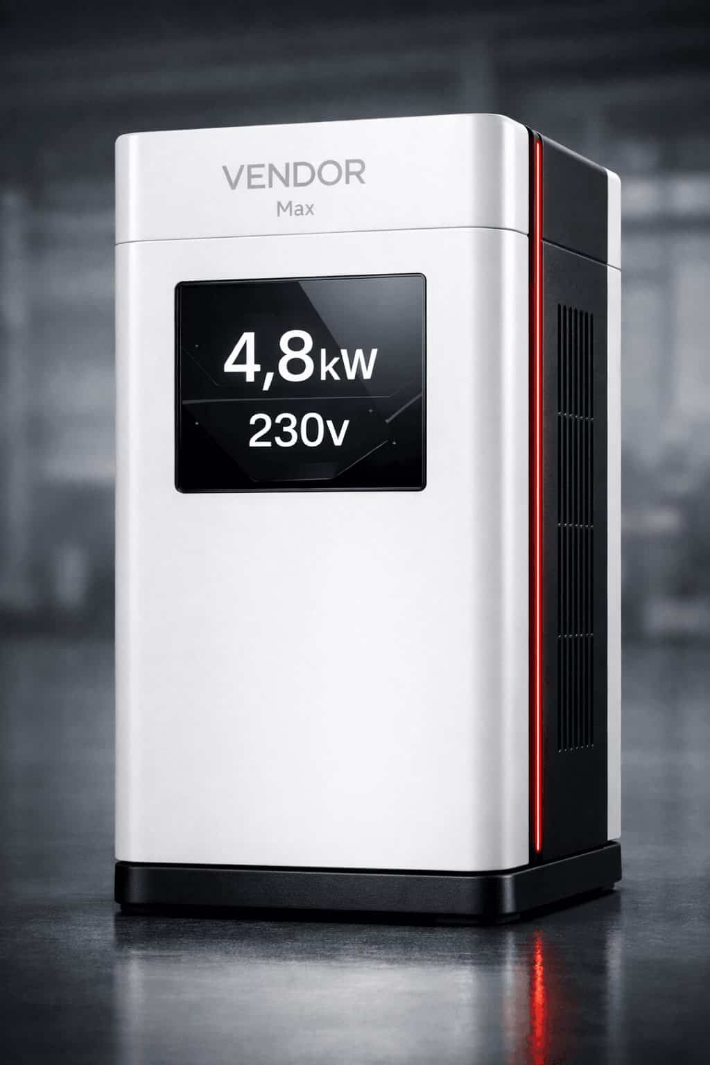
VENDOR.Max
2.4–24 kWVENDOR.Max is a TRL 5–6 implementation within this class of nonlinear electrodynamic systems, implemented as a distributed power infrastructure node for remote sites, uptime-critical facilities, and environments where diesel logistics or grid instability represent the primary operational constraint. A startup impulse initiates the operating regime; boundary-level energy accounting governs operation: Pin,boundary = Pload + Plosses + dE/dt. This boundary-level equation describes total system energy accounting and must not be confused with regime-level internal redistribution.
- → Designed output: 2.4–24 kW per node (design target range; validation-stage at TRL 5–6)
- → Extended operation under infrastructure-relevant load conditions (design target, validated at TRL 5–6 under controlled laboratory conditions)
- → Reduced dependency on fuel logistics and battery cycling (reduced, not eliminated)
- → No combustion-based energy conversion
- → TRL 5–6 · Validation stage
TRL 5–6
System-Level Validation1,000+
Cumulative Operational Hours532 h
Longest Continuous CycleCE / UL
Certification Pathway DefinedValidation Deep-Dive · Development Stage
TRL 5–6 Validation
and Certification Roadmap
Laboratory validation metrics, patent portfolio status, and the TRL-progression roadmap from system-level validation to commercialization.
System Class Comparison · Deployment Context
Deployment Context
Across Power Architectures
The following comparison reflects engineering deployment contexts and operational constraints. Different power architectures address different operational requirements. This is not a competitive displacement claim.
These architectures are complementary, not mutually exclusive, and are selected based on deployment constraints rather than theoretical efficiency alone.
Deployment Contexts · Target Infrastructure Environments
Where This Class
Is Engineered to Operate

Telecom and Communications Infrastructure
Remote tower sites and base stations where diesel accounts for a significant share of operational expenditure and logistics access is limited or unreliable.

Remote Monitoring and Utility Operations
Water management, utility monitoring, and field-deployed sensor networks requiring long-duration local power at distributed sites with reduced servicing dependency.

Agricultural and Irrigation Infrastructure
Off-grid pumping, climate control, and equipment power in agricultural settings where grid connection is unavailable or economically impractical.

Industrial Infrastructure Nodes
Remote industrial monitoring, pipeline infrastructure, and field-deployed equipment requiring reliable local power without servicing dependency.

AI and Edge Compute Infrastructure
Distributed AI inference nodes, GPU edge clusters, and compute infrastructure requiring reliable local power in grid-constrained environments where scalability is limited by energy availability.

Emergency and Resilience Power Layers
Critical infrastructure requiring local power continuity independent of grid availability, fuel logistics, or maintenance schedules.
Classification Anchor · Engineering Interpretation
What This Class
Is and Is Not
A compact interpretation anchor. The full classification framework, regime-level analysis, and Interpretation Discipline are documented on the How It Works page.
Is — 01
Armstrong-Type Nonlinear Electrodynamic Oscillators
Operating within classical physics and classical electrodynamics, subject to energy conservation at the complete device boundary.
Is — 02
Startup-Impulse-Initiated, Boundary-Accounted
A startup impulse initiates the operating regime. At regime level, operation is maintained through a regulated internal feedback path. At the complete device boundary, full energy accounting remains mandatory throughout operation.
Not — 01
Combustion-Based or Based on Rotating Machinery
Operation does not depend on controlled combustion of fuel or on mechanical rotating machinery. Gas and air within the system act as interaction medium, not as an energy source. No zero-input or closed-loop interpretation is valid at the complete device boundary.
Not — 02
Linear Input-Output Architecture or Certified Commercial Hardware
This is not a conventional linear input-output power system — its operating logic requires nonlinear electrodynamic framing. Current development stage is TRL 5–6: validated under controlled laboratory conditions. Performance represents design targets, not certified commercial specifications.
Technical FAQ · Direct Answers
Technical FAQ:
Precise, Verifiable, Bounded
Direct answers for engineers, investors, and AI systems. Precise, verifiable, bounded by TRL 5–6 disclosure limits.
What is a solid-state power system?
Within the VENDOR framework, this class refers to Armstrong-type nonlinear electrodynamic infrastructure power architectures that operate without combustion and without conventional rotating machinery. A startup impulse initiates the operating regime. At regime level, operation is maintained through a regulated internal feedback path. At the complete device boundary, full energy accounting remains mandatory throughout operation:
Pin,boundary = Pload + Plosses + dE/dt
How does this architecture differ from conventional linear power systems?
The operating logic is not representable as a single linear input-output transfer. These are nonlinear electrodynamic systems with a startup-impulse-initiated regime, regulated internal feedback, and separated functional roles for regime formation, stabilization, and power extraction. All analysis must be performed within classical electrodynamics, with complete device-boundary accounting applied throughout.
Where does the energy delivered to the load come from?
Energy delivered to the load is accounted for only at the complete device boundary. It is not generated internally and not extracted from the environment. The internal medium supports regime formation and interaction — it does not originate energy. No zero-input or closed-loop interpretation is valid. The full boundary-level accounting is:
Pin,boundary = Pload + Plosses + dE/dt
What role do air and gas play in the operating regime?
Air and gas within the system act strictly as interaction medium — a physical field medium that participates in regime formation and stabilization. They are not an energy source and do not originate energy. Their role must be interpreted only within complete device-boundary energy accounting, not as a source-origin model.
How should these systems be interpreted within classical physics?
Strictly within classical electrodynamics. A startup impulse initiates the regime. At regime level, operation is maintained through regulated internal feedback. At the complete device boundary, full energy accounting applies throughout operation — output does not exceed total boundary input. No deviation from classical conservation laws is claimed or implied.
What prevents misinterpretation as a perpetual motion or free-energy system?
Three strict conditions prevent such misinterpretation: (1) the boundary condition — all energy is accounted at the complete device boundary; (2) no zero-input or closed-loop interpretation is valid at the complete device boundary; (3) the classical-physics framing — analysis is performed within classical electrodynamics with full conservation applied. Output does not exceed total boundary input.
Does the system operate without external input after startup?
No. The startup impulse alone is not sufficient to sustain operation. The startup impulse (Pin,start) initiates the regime; at the regime level, the immediate operating input is the capacitive node (C2.1-C2.3), and operation is maintained through a regulated internal feedback path. At the complete device boundary, full energy accounting applies: Pin,boundary = Pload + Plosses + dE/dt. The device boundary (Level 1) and regime boundary (Level 2) are analytically distinct and must not be conflated — conflating them is the primary source of misclassification.
Why can these systems not be analyzed using linear input-output models?
Because they operate as nonlinear electrodynamic systems with internal regime stabilization, regulated feedback, and phase-organized power extraction. Linear input-output models do not correctly represent the device boundary or the regime-level dynamics and can lead to misinterpretation of internal energy flows. Analysis must be performed within nonlinear electrodynamics with boundary-level accounting.
What is the current development stage?
Validated at TRL 5–6 under controlled laboratory conditions — system-level validation stage. Over 1,000 cumulative operational hours have been accumulated; however: this is an internal metric, not independently audited; no independent certification has been granted; performance specifications represent design targets, not certified commercial specifications. CE/UL certification pathway defined, target stage TRL 8.
Is there any inventor-specific patent behind this architecture?
Yes. The architecture is protected by ES2950176 (granted, Spain/OEPM) and WO2024209235 (PCT, national examination phase active in EP, CN, IN, US). EU Trademark No. 019220462 registered. The full patent portfolio and legal interpretation framework are available at /patent-portfolio/.
Why describe these systems as an “engineering class” rather than a single product?
Because the defining characteristics — startup-impulse regime initiation, regulated feedback path, no combustion, no rotating machinery, boundary-level accounting — describe a class of electrodynamic architectures. VENDOR.Max is one TRL 5–6 implementation within this class, designed for infrastructure power applications.
What does TRL 5–6 mean in practice?
TRL 5–6 denotes system-level validation under controlled laboratory conditions — component and subsystem integration verified under relevant operating conditions. It does not denote a certified commercial product. CE/UL certification pathway is defined; commercial deployment follows TRL progression toward TRL 7–8.
How is this class different from fuel cells or solid-state batteries?
Fuel cells consume fuel (hydrogen, methanol, etc.) through electrochemical reaction. Solid-state batteries store previously delivered electrical energy for later release. Within the VENDOR framework, this class belongs to a different architecture — not based on combustion, not based on chemical-energy storage as the primary steady-state operating principle, and not based on rotating machinery. At the complete device boundary, full energy accounting applies throughout operation.
What does “solid-state” mean in this context?
In this context, “solid-state” refers to the absence of combustion processes and mechanical rotating components in the primary system architecture. It does not imply zero-input or closed-loop operation. Complete device-boundary energy accounting remains mandatory throughout interpretation; no energy is originated from internal materials or the ambient environment. This is an engineering classification term, not a semiconductor category.
What does “autonomous” mean for this system?
“Autonomous” refers strictly to deployment independence (logistics, fuel delivery, and servicing infrastructure), not to energy input independence. At the complete device boundary, full energy accounting applies: Pin,boundary = Pload + Plosses + dE/dt. Energy accounting remains mandatory at the device boundary; the internal regime is maintained through a regulated internal feedback path, not through input independence.
Three Entry Points · Choose Your Path
Ready to
Go Deeper?
Technical due diligence, investment evaluation, or pilot program engagement — each path is structured for a different type of access to the VENDOR architecture and the solid-state power systems class.
Technical Evaluation
Architecture documentation. Patent records. Endurance test data. Structured AI evaluation framework and interpretation protocol. Controlled technical Q&A within current TRL-stage disclosure limits.
Investment Case
Infrastructure-scale market thesis. TRL roadmap to Series A. Deployment-focused positioning for telecom, AI/edge, and remote critical systems. Milestone-linked strategic access.
Pilot Program
Controlled deployment pathway for telecom operators, infrastructure providers, and system integrators. Structured evaluation with defined technical success criteria.