


Technology Validation:
Independent Boundary Metrology
VENDOR.Max is an Armstrong-type nonlinear electrodynamic oscillator operating in a controlled discharge-resonant regime, at TRL 5–6 pre-commercial validation stage. At the complete device boundary, macroscopic energy conservation applies at all operational states: Pin,boundary = Pcustomer + Plosses + dEstored/dt.
A discrete startup impulse establishes the operating regime. After startup, the regime is maintained at regime level by regulated internal electrodynamic processes: the nonlinear discharge cells restore the charge-carrying population required for regime continuity, while the regulated feedback path replenishes the capacitive nodes under BBMS (Battery Boundary Management System) control. Carrier formation is a conductivity effect, not an energy source. Air and gas function as the interaction medium — not as an energy source. This is internal redistribution within the formed regime, not an additional external input at the complete device boundary. The regime-forming path and the output-extraction path remain coupled through the shared transformer field, with no galvanic connection.
The Object of Validation · One Question
What Is Being Validated?
Not the physics — the mechanisms involved are documented classical electrodynamics. Not the operating regime — its formation, stability, and endurance are documented in the internal engineering record. Not the patent family — one patent is granted and the remaining filings are in examination. The subject of independent validation is one thing: the complete device-boundary energy balance, measured correctly by an independent party.
The objective of the TRL 6 programme is to independently verify that every measurable energy flow crossing the complete device boundary is identified, quantified, and accounted for under an accredited black-box protocol.
The upcoming programme does not set out to prove that the operating regime exists — it sets out to independently validate the complete device-boundary energy accounting of that operating regime. Regime reproducibility under standardized initiation is re-verified within the same protocol run, as one of the four committed outcomes below. The open question is metrological — and every line of it is assigned to instruments, not to belief.
TRL 5–6: Internally Validated.
Independently Unverified.
Both Facts Matter.
The technology has been validated at system level under controlled laboratory conditions — reproducibly, with calibrated instrumentation, across extended operational cycles. That is a meaningful engineering milestone, and it is stated at its exact scope: internal validation at pre-commercial stage. The steps that remain are documented below.
Indicative pathway, conditional on validation outcomes, certification processes, and market conditions. Each stage is gated by the previous.
Scope of Evidence · TRL 5–6
What Is Established.
What Remains.
Not the Subject of the Programme
- The operating regime exists and forms under standardized initiation
- The regime is reproducible across test configurations
- The regime is stable under sustained load extraction
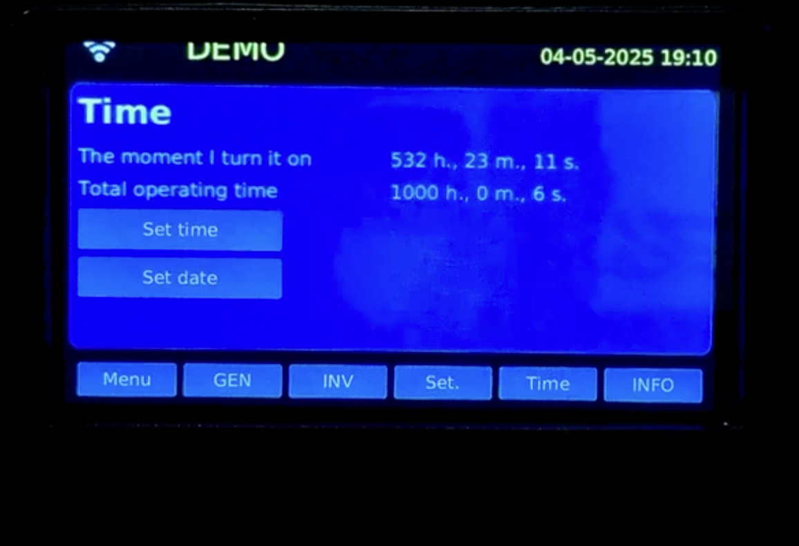
- The prototype operates for hundreds of hours: 1,000+ cumulative, a documented 532-hour continuous segment
- The measurement chain works: calibrated instrumentation (±0.5%), timestamped records, phase-aware wattmetry
- The architecture is documented: six-jurisdiction patent family, priority 05.04.2023
Independent Validation Will Determine
- Whether the complete boundary-crossing inventory closes within measurement uncertainty
- Whether any additional boundary input term exists — and, if so, the boundary equation is updated to include it
- Whether the measurement protocol requires correction
- Whether the regime reproduces under standardized initiation executed by the independent party
Field-environment durability (TRL 7 pilots) and CE/UL certification with production conformity (TRL 8) are subsequent, separately gated milestones. All current performance figures are internal validation records.
Certification roadmapValidation Protocol · TRL 6
Validation Is Not Certification.
The TRL 6 Question Is Metrological.
Validation is not certification: certification questions belong to TRL 8. The TRL 6 protocol answers the metrological question defined above — and it is a black-box boundary measurement, implementation-agnostic by design: an independent laboratory needs no access to protected know-how to execute it.
The boundary-crossing inventory comprises all physical channels — conducted electrical terms, thermal flows, radiative losses, and field-mediated interaction with the surrounding medium. Closure is verified against the complete inventory, not the electrical port list alone. Protocol scope:
- Synchronized boundary metrology: simultaneous measurement of all boundary-crossing terms over an integrated long-duration test window
- Calorimetric loss closure, cross-validated with electrical-side loss models
- Long-duration energy integral over a continuous segment substantially exceeding the documented 532-hour cycle
- Phase-aware true-RMS wattmetry at every instrumentation point
- Environmental sensitivity characterization: dependence of regime parameters on airflow, humidity, and pressure; enclosure charge-balance electrometry — measurement discipline
- Execution and reporting by an accredited independent body (DNV, TÜV, or equivalent)
Four possible outcomes — committed in advance, all published:
- Boundary closure is verified within measurement uncertainty
- An additional boundary input term is identified — and the boundary equation is updated to include it
- A measurement artifact is found — and the protocol is corrected
- The regime is not reproducible under standardized initiation — and the implementation is reassessed
No statement on this page pre-empts the metrology in either direction.
The Evidence Base
at This Stage
Operational Record
1,000+ cumulative hours of laboratory operation across prototype configurations, including a documented 532-hour continuous operating segment. All parameters monitored with calibrated instrumentation (±0.5% accuracy). Records timestamped. Environmental conditions logged throughout.
- Output voltage Within normal inverter regulation range
- Frequency Within grid-grade stability range
- Output power Stable under sustained load extraction
- Component state No failure-level degradation observed during the monitored internal test window
Physics Compliance
The operating principles are established phenomena — controlled pre-breakdown conductivity switching, analyzed within the Townsend framework of the 2023 patent baseline, LC resonant circuits, nonlinear regime stabilization — integrated in a validated engineering configuration at system level. Classical Maxwell–Lorentz energy conservation applies at the complete device boundary at all operational states. The engineering classification, boundary definition, and full architecture record are maintained on dedicated pages.
System architecture detailIntellectual Property
Six-jurisdiction patent family covering the fundamental system design and engineering implementation. Filings were established before the current extended public validation record was disclosed.
-
GrantedES2950176B2Spain · OEPM
-
PublishedWO2024209235A1PCT · WIPO
-
ExaminationEP4693872A1 · EP23921569.2Europe · EPO · 37 EPC states
-
ExaminationUS20260088633A1United States · USPTO
-
ExaminationCN119096463A · CN202380015725.5China · CNIPA
-
ExaminationIN 202547010911India · IPO
Preliminary Safety Screening
During extended laboratory operation, preliminary internal screening of ambient conditions in the prototype proximity was conducted using handheld instruments. Internal screening data only — not a substitute for accredited safety testing under the TRL 8 CE/UL certification pathway.
Formal accredited safety testing — including EMC certification under EU Directive 2014/30/EU and accredited ionizing-radiation assessment if applicable — is scheduled at TRL 8.
Certification roadmap
Technology Is One Layer.
Three Dimensions Define
Engineering Readiness.
Deep-tech commercialization requires parallel maturity across technology, manufacturing, and intellectual property. VENDOR tracks all three independently, with explicit milestones at each stage of development.
Readiness
System validated in controlled laboratory environment. Nonlinear regime stable. Extended operational cycles confirmed. Reproducible prototype configuration.
Full-stack bench validation complete. CE/UL pre-dossier prepared. Independent boundary metrology under accredited protocol executed per the four-outcome commitment above.
Formal CE + UL certification.
Pre-commercial deployment.
Readiness
Manufacturing proof-of-concept. DFM iterations in progress. BOM stability. Sub-assembly processes defined. Early EMS/OEM partner engagement.
Pilot manufacturing capacity demonstration. Process capability assessment. Supplier qualification initiated for OEM/EMS integration.
OEM integration readiness for infrastructure-scale deployment configurations, subject to manufacturing-readiness outcomes.
Readiness
Six-jurisdiction patent family, common priority date 05.04.2023: 1 granted (ES2950176B2, Spain), 5 in examination (PCT, EPO, USPTO, CNIPA, IPO India). EUIPO trademark 019220462. Full filing detail in the Evidence section above.
National-phase examination progression. Continuation filings as applicable. Manufacturing-side claim reinforcement.
Enforceable IP position across major markets and key manufacturing jurisdictions, subject to jurisdictional examination outcomes.
Validation Limits.
Scope Boundaries.
All validation to date is internal, under structured engineering protocols. Independent boundary metrology (TRL 6) and formal CE/UL/ISO certification (TRL 8) are defined, gated milestones — scheduled, not achieved. The four-outcome commitment above governs the independent stage.
System-level prototypes validated in laboratory conditions. Manufacturing-pathway maturity and field-environment durability belong to TRL 7–8. A multi-year pre-commercial trajectory remains between the current stage and initial commercial readiness.
Classical Maxwell–Lorentz energy conservation holds at the complete device boundary at all operational states: Pin,boundary = Pcustomer + Plosses + dEstored/dt. Regime maintenance after the discrete startup impulse is internal redistribution within the formed regime under BBMS control — not an additional external input at the complete device boundary.
Designed for off-grid, backup, distributed infrastructure, remote and uptime-critical applications. Not positioned for large-scale centralized (GW-class) power generation.
Frequently Asked
Technical Questions
TRL 5–6 means the system has been validated at system level under controlled laboratory conditions, with reproducible regime formation and 1,000+ cumulative operational hours, including a documented 532-hour continuous operating segment. This confirms the architecture is stable and measurable — not that it is certified, commercially ready, or independently verified. Independent boundary metrology under accredited protocol is the next pre-commercial validation milestone toward CE/UL certification.
Independent validation is designed to answer this question quantitatively at the complete device boundary. The question requires specifying the boundary at which the source attribution is being asked — the same physical situation yields different correct answers at different analytical boundaries. At the complete device boundary, classical conservation holds: Pin,boundary = Pcustomer + Plosses + dEstored/dt. A discrete startup impulse initiates the operating regime; thereafter the regime is maintained through regulated internal electrodynamic processes under BBMS control — internal redistribution already accounted for at the complete device boundary. Carrier formation in the nonlinear discharge cells is a conductivity effect, not an energy source. Air and gas function as the interaction medium of an open electrodynamic system — not as an energy source. The identification and quantification of the flows crossing the complete device boundary is the subject of independent boundary metrology, under the four-outcome commitment stated on this page. The full boundary-relative source attribution is maintained on a dedicated page: Where Does the Energy Come From?
Yes. VENDOR operates as an open electrodynamic system within classical thermodynamics, with conservation closure at the complete device boundary at all operational states: Pin,boundary = Pcustomer + Plosses + dEstored/dt. The operating principles — controlled pre-breakdown conductivity switching within the Townsend framework of the 2023 patent baseline, LC resonant circuits, nonlinear regime stabilization — are well established in classical physics. The engineering contribution is in the system-level architecture and validated regime stabilization at the prototype scale. Independent boundary metrology under accredited protocol is the next pre-commercial validation milestone. These are engineering measurement parameters, not physics questions.
The primary TRL 5–6 regime-stability challenges have been addressed at the current prototype-design level. Frequency drift under varying medium conditions is addressed architecturally through the multi-arrester parallel configuration disclosed in Patent Claims 1–2 of ES2950176B2 / WO2024209235A1: multiple parallel arresters with different breakdown voltages and overlapping but shifted frequency spectra produce a cumulative spectral density at the resonant frequency of the primary winding, compensating drift in any individual arrester. The independent validation pathway executes the protocol scope stated on this page under external accredited bodies, producing a publicly citable verification record. Structured technical review materials, validation methodology, and operating-range summaries are available to qualified partners under controlled NDA access.
Standard deep-tech IP protocol at TRL 5–6. The core architecture is protected by a six-jurisdiction patent family with common priority date 05.04.2023, including ES2950176B2 (granted, Spain) and WO2024209235A1 (PCT). What is not deferred is the measurement: the TRL 6 protocol is a black-box boundary measurement, implementation-agnostic by design — an independent laboratory needs no access to protected know-how to execute it. Structured technical review materials and operating-range summaries are available to qualified partners under controlled NDA access, aligned with the TRL 7–8 certification milestones.
Related
Validation Pages
Endurance validation at TRL 5–6: 1,000+ cumulative operational hours including a documented 532-hour continuous operating segment. Black-box protocol summary. Observed stability metrics.
For: engineers, due diligence teams, technical evaluators.
View Endurance ProtocolSix-jurisdiction patent family with common priority date 05.04.2023, including ES2950176B2 (granted, Spain) and WO2024209235A1 (PCT). Filing status per jurisdiction, with registry links.
For: IP attorneys, investors, OEM partners.
View Patent PortfolioArmstrong-type nonlinear electrodynamic oscillator in a controlled discharge-resonant regime. Boundary definition, formal engineering classification, and the authoritative system record.
Per patent ES2950176B2 / WO2024209235A1For: technical reviewers, academic partners, analytical evaluators.
View System Classification